Simply thinking outside the box!
Simply variable.

Setup could not be any easier

  • When mounting by screwing onto the base plate, only use posts with a length of 2.20 m. The maximum construction height of 2 m (upper edge of the floor to the upper edge of the post) may not be exceeded. Caution: Higher structures do not correspond with the static requirements.
  • Holes are to be pre-drilled 0.5 mm smaller than the screw diameter. In order to ensure a full seating, sink the drill holes for bar connectors. Ensure that the clearance from the edge is at least 10 mm.
  • When mounting the posts and the bar, ensure that you keep to a clearance of 12 mm so that the construction is able to expand without pressure if necessary.
  • The full engagement of the bar connectors when performing the final assembly ensures complete stability.
  • Assembly and production-related tolerances regarding length, width and thickness are to be taken into account during assembly and the dimensions on the construction must be examined once again.

Simple Assembly

Simple assembly for all fence designs

This EasyDeck® construction manual is the basis for all versions of fence assembly. Only use original EasyDeck® articles and simply follow our processing recommendations to ensure that our warranty does not become void.

EasyDeck® fences can be adapted to individual requirements via the online planner. In order to ensure that assembly is easy, we can pre-assemble all elements on your behalf if requested. This means that you do not need to perform the time-consuming pre-drilling of required holes or adaptations of diagonal section and you can simply start with the assembly!

Simply plan your individual fence online:

Installation which is adapted to the slope

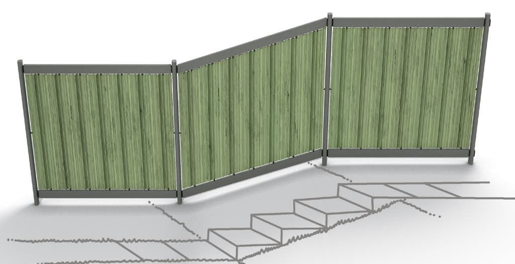
Gradients in the terrain? Not a problem for the EasyDeck® privacy screen or the EasyDeck® bar fence.

The EasyDeck® system sizes can be installed on inclines measuring up to 3%. When dealing with gradients below 10%, use the special lengths or the fence field set with stainless steel bar. Greater differences in height in the terrain can be individually adapted by diagonal cuts to the bar and on the element.
Angle structure
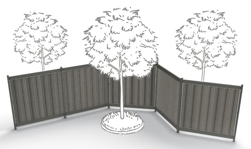
The oval EasyDeck® post shape and the innovative bar connector allow the bar fence and privacy screen to be positioned with a free choice of angle.

Anchoring options

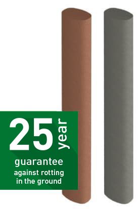
EasyDeck® posts are durable, even when installed in the ground. We offer you a 25 year guarantee against rotting. You can choose between encasing the posts in concrete or on base plates.

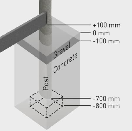
Simply encase the posts into concrete
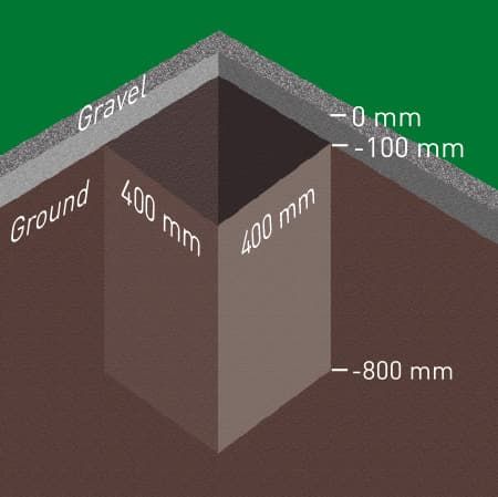
Dig all of the foundation holes (400 x 400 x 800 mm).
Fill the foundation hole with concrete to a depth of 100 mm. Position the frame in the foundation hole at a depth of -700 mm. Precisely apply the lower edge of the post with the aid of a small brick. Apply concrete into the foundation hole to a level of -100 mm. All posts must be vertically aligned.

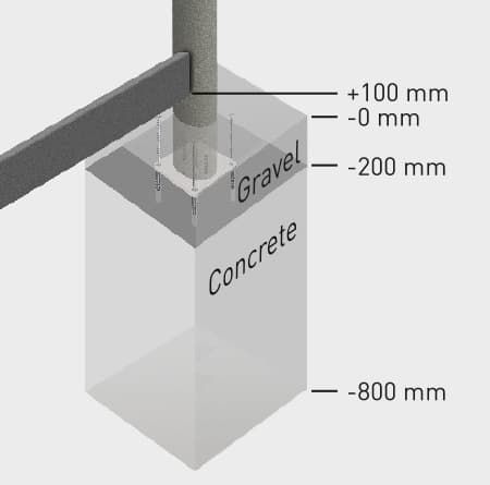
Simply assemble the posts on the base plate
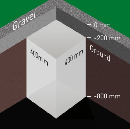
A separate, suitable foundation is required. For this purpose, dig all of the foundations holes (400 x 400 x 800 mm) and fill with concrete to a height of between -800 mm and -200 mm. Allow to fully harden. Alternatively, a suitable anchoring system can be installed on-site.
Pre-drill the holes on the post for the base plate (75 x 850 mm). Screw the base plate to the oval post (3 M8 x 80). Fasten the base plate complete with post to the foundation using a suitable anchoring system. All posts must be vertically aligned.

Assembly process of the “Blickfang” privacy screen fence

The frame construction

1. Assemble connecting parts
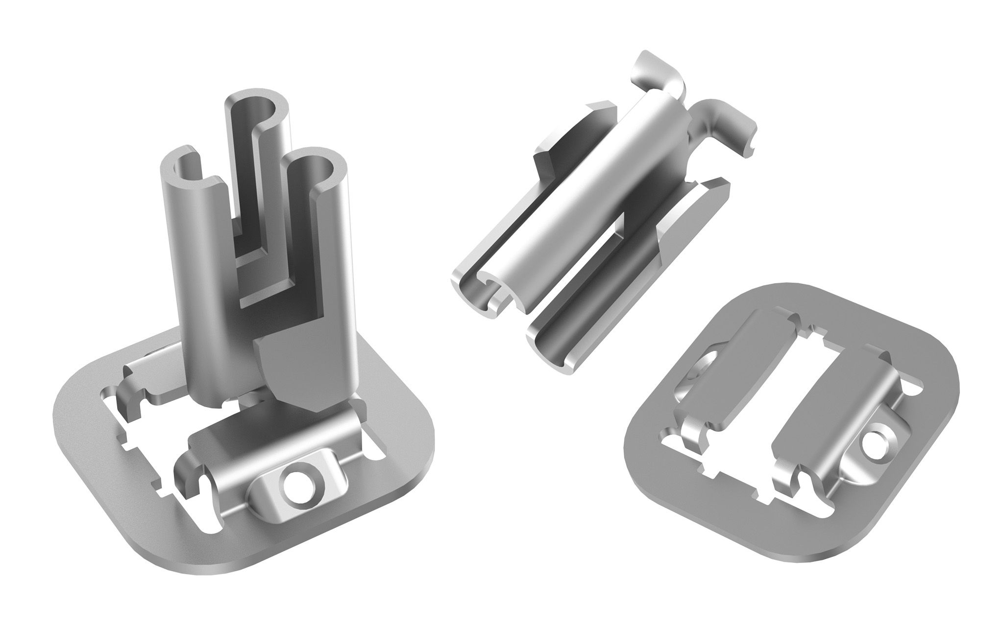
Screw the “Post” connecting part of a bar connector to the post. On the frontal sides of the bar, centrally position, mark, and screw on the “Bar” connecting part. Using a 5.5 mm drill, pre-drill and countersink the holes to 35 mm.
2. Engage the lower bar
Fully engage both bars on the post.
3. Position the frame
Position the pre-assembled frame and vertically fasten it in the foundation (encased in concrete or screwed). Prepare all further frames. In order to do so, screw the bar connector to the next post and bar according to the instructions (see item 1). Attach the post in the foundation vertically andengage the upper and lower bars.

Simple panel assembly with the GCC bar
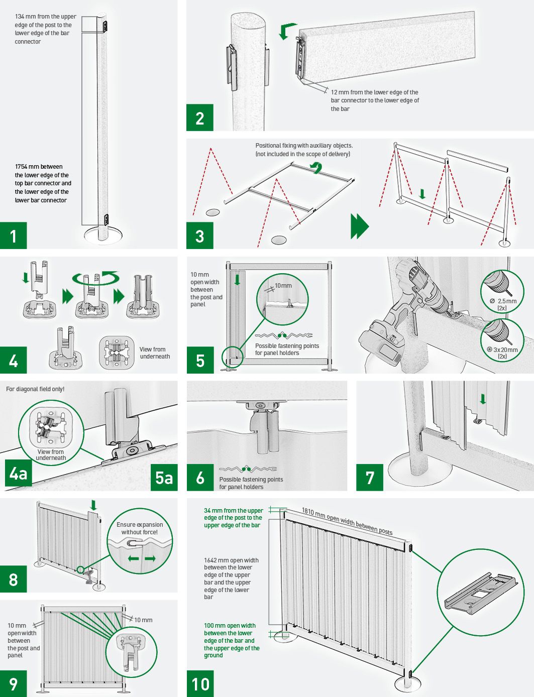
4. Fasten the panel holder
Insert the panel holder into the holding plate; turn it beyond the latching moment and centrally position the panel holder in the holding plate.
4a. Fasten the panel holder (diagonal field)
For the diagonal field, position the panel holder with the hook at the lower stop of the holding plate.
5. Insert the panel
Push the lower panel holder on the first panel centred at the first bead (left or right). Place this panel between the bars starting 10 mm from the post, align the holding plate on the bar chamfer, determine the bore in the lower bar, and mark it precisely. Pre-drill with 2.5 mm drill and fasten with 3 x 20 mm screws.
5a. Insert the panel (diagonal field)
For the diagonal field, start panel setup from below. Always let the panel holder hit the lower stop of the holding plate as a fixed point in order to ensure even expansion of the panels. Align the holding plate on the bar, pre-drill and screw it on.
6. Fix panel holder
Push on the upper panel holder with the holding plate centred on the highest bead of the first panel and fasten it according to the instructions (see item 5).
7. Connect the further panels
In the following panels, push on the lower panel holders with the holding plate centred on the highest bead and connect the panel with the previous one by pushing it in.
8. Pay Attention to the last panel
Fasten the lower panel holders according to the instructions (see item 5). Ensure that the panels can expand without force. Let the last panel end 10 mm from the post.
9. Equip the upper edge of the panel
After attaching all lower panel holders, push on the upper panel holders with the holding plates and fasten them according to the instructions (see item 5). Also ensure expansion of the panels without force.
10. Apply the top bar
Install the next fence field in the same manner.

Please use our fence configurator for individual structures, e.g. inclined adaptation to the slope:

Bar fence assembly procedure

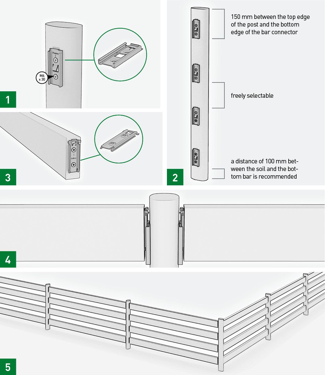
1. Screw the „Post“ connecting part
Screw the „Post“ connecting part to the post. Pay attention to the „TOP“ labelling. Using a 5.5 mm drill, pre-drill and countersink the holes to 35 mm.
2. Go on
Screw the „Post“ connecting part to the post at equally spaced intervals. Please note that the bottom fence bar has a gap measuring at least 100 cm to the ground.
3. Screw the bar
Centrally position, mark, countersink and screw the „Bar“ connecting part to the frontal sides of the bar.
4. Insert the bars
Insert the bottom and top bars but do not fully engage the top bar.
5. Position the frame
Position the pre-assembled frame and vertically concrete/screw into the foundation. Please see Anchoring options. Once the concrete has set or after the screwing process has been completed, remove the top bar, insert all of the missing bars from beneath and fully engage.

Article overview for the assembly of the „Blickfang“ privacy screen fence

Post

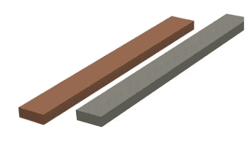
Dimensions: 60 x 90 mm
Colours: Terra and Graphite
Lengths: 220 cm, 270 cm
(available in a 360 cm version for structures which are adapted to the slope)

Panel

Maße: 35 x 270 mm
Länge: 160.2 cm
(available in a 210 cm version for structures which are adapted to the slope)
Thickness: 6 mm
Colours: Jade, ecru und platin
Requirement: 7 units per field

Panel holder

Requirement: 14 units per field
(with 7 panels), incl. mounting disc and screws
Material: Stainless steel,

Bar

Dimensions: 40 x 112 mm
Colours: Terra and graphite
Länge: 178.6 cm
(available in a 360 cm version for structures which are adapted to the slope)

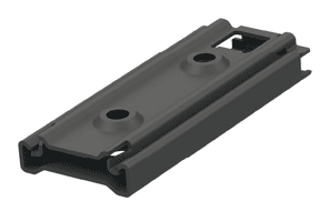
Bar connector, two-party
Post/bar

Requirement: 2 parts per bar
Material: Blackened stainless steel incl. 4 screws (M6 x 30 mm) per connector
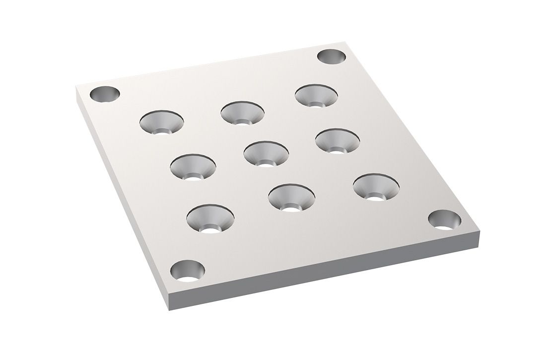
Base plate – post

Dimensions: 120 x 140 mm
Requirement: 1 unit per post
Material: Steel galvanised
Thickness: 8 mm
incl. 3 screws (M8 x 80 mm) per plate

Door and gate

Dimensions: 102 x 185 cm (Frame: 112 x 270 cm)
Colours: Frame: Terra and graphite, Panels: Jade, ecru and platin

Incl. fittings, pre-aligned for profile cylinders. Production available on request.

Attention: Connect the frame to the post in a force-locking manner using 5 M8 x 80 screws per side, connect and then encase into concrete together